Homemade Graded-Z Shield for a Gamma-ray Spectrometer
The Radiacode Gamma spectrometers, though not cheap in an absolute sense, are cheap enough to be accessible to many and make gama-ray spectroscopy accessible to people who would never have considered buying a more typical laborartory instrument. They are remarkably capable for the price. At home, my Radiacode 103 typically sees an environmental background radiation of about nine counts-per-second (9 CPS). This is likely higher than for many people through a combination of my altitude (over 5000' above sea level) and local geology. To get the best possible signal from weak sources I wanted to create a screened enclosure to block off the ambient background and see just the sample of interest.
The lead box
X-ray attenuation coefficients, both theoretically derived and measured in the laboratory, are widely published, with the standard reference values being the NIST X-Ray Mass Attenuation Coefficients (DOI 10.18434/T4D01F). The attenuation coefficient $\mu$ is defined as the probabilty of any individual photon intereacting with the medium through which it is passing, per unit length. This gives rise to an exponential decrease in the number of photons following the equation
$$ { N \over N_0 } = {\rm exp} \Big[ -\mu x \Big] $$
where $N_0$ is the number of incident photons before entering the attenuating medium, $N$ is the number of photons emerging in the attenuated beam and $x$ is the path length in the material. Using this formula and published attenutation coefficients we can select a suitable material and the thickness needed to block any given particular signal. In this case we wish to block the typical enviromental background which would otherwise contaminate all measurements.
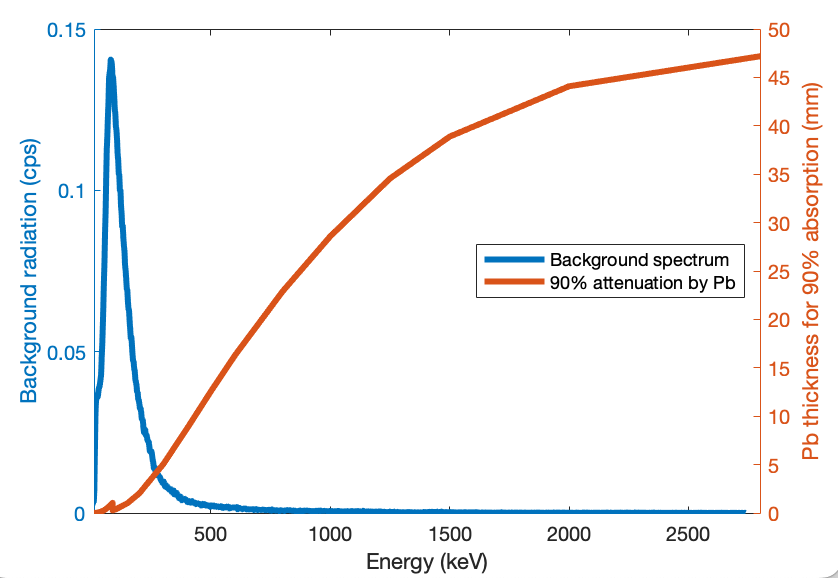
Figure 1 shows the thickness of lead shielding required to absorb 90% of photons as a function of energy, over the full range covered by the Radiacode 103. At the highest energies (2.8MeV) I need almost 5cm of lead. Fortunately, the vast majority of the background is at low energies which are much easier to block. The lead sheets I have easily available are 1.6mm. That will block 90% of signal at 180keV. Two layers will block 99% of signal at 190keV and 90% at 245keV. From the plot in Figure 1 we see that this will eliminate most of the background which is dominated by energies <300keV.
The graded shield.
Clearly less than 5mm of lead is sufficient eliminate most of the background and even 1–2mm will provide a significant reduction. There is a further problem though; X-ray fluorescence. Any material bombarded by high energy gamma rays will start to glow (fluoresce) at certain specific engeries. A small fraction of the energy that is absorped will get re-radiated at energies determined by the electron structure of the atom in question. For lead, this fluorescence peak is around 80keV. This means that using my thin lead sheeting alone as a screen, the background will be effectively blocked over all energies up to around 300keV, but the shielding itself will be creating a new signal inside the shielded box, just in a narrow band around 80keV.
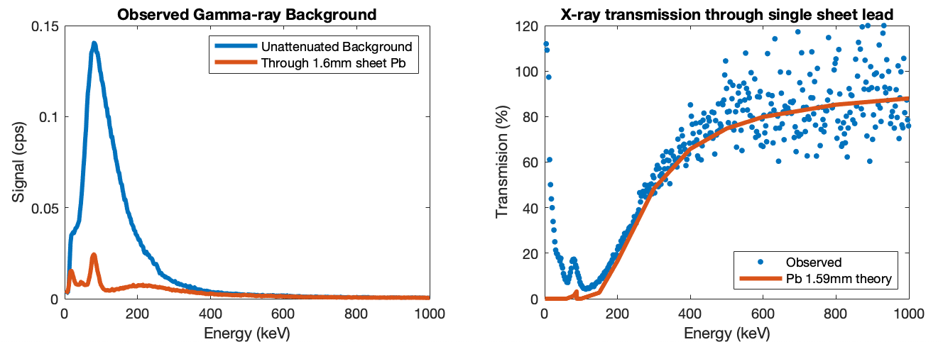
This phenomenom is demonstrated in Figure 2. A small biscuit tin was lined internally with 1.6mm lead sheet and observations taken of the background with the device outside and inside this box. The left panel shows the observed background and the attenuated background when the instrument is inside the lead box. The background is hugely reduced, but the 80keV peak from X-ray fluorescence appears. The right panel shows the ratio ('with lead' divided by 'without lead') to give the transmission per cent. Overlaid is a line showing the prediction for 1.6mm of lead, using published X-ray mass attenuation coefficients (DOI 10.18434/T4D01F). My data does not perfectly fit the prediction and seems to be behaving like about 1.4mm of lead. Maybe my lead sheeting is thinner than I think or I have a small leak in the sealing of my lead lined box.
The solution is to add another shield, made of a different material, between the lead and the instrument. By selecting a material that absorbs well around 80keV we have a multi-layer screen where the lead blocks most of the background, but creates an unwanted new signal at 80keV. Then the second layer is able to block just that 80keV signal. Both the ability of an atom to block gamma rays and the energy at which they fluoresce are determined by the atomic mass. The heavier the atom, the better it blocks high energy photons and also the higher the energy of the X-ray fluorescence peak. The optimum choice here is something from the periodic table around indium, cadmium, antimony and tin. Though pure tin is not commonly available, modern pewter is typically 92% tin and 6% antimony, so a lead-free pewter (98% composed of tin and antimony) is a near perfect choice for the second layer in screen. I was able to buy a second hand pewter jewelry box very cheaply. Some pewter contains lead, so though it would likely be a big improvement over the lead-only box, it would not be ideal since the lead in the pewter would still be fluorescing at 80keV.
In physics you never get something for nothing. The pewter (tin and antimony) blocks the 80keV emmission from the lead, but it in turn fluoresces around 25keV. We need to add another layer to block that. Copper is readily available, reasonably cheap and effective at blocking 25keV, so that makes the third layer. Copper fluoresces at 8keV. We could add a fourth layer to block that. Aluminium foil would do a good job, but in fact there is no need. The cesium iodide crystal in the Radiacode 103 is only sensitive above 20keV. It will not see the 8keV emission from the copper. By using the multi-layered structure, we have progressively pushed the fluorescence peak down to an energy too low for the instrument to detect.
In summary
- Use as much lead as available to block as much background as you can. In this example, 1.6mm lead blocks more than half of gamma rays at 300keV
- The lead itself glows at around 80keV
- Anything over 1mm of tin effectively blocks the 80keV X-ray fluorescence from the lead, but then itself glows at 25keV
- A thin (0.1mm) copper foil blocks the 25keV X-ray fluorescence from the tin, and then itself glows at 8keV
- The 8keV photons are too low an energy to be detecdted by my instrument
Testing the theory; Pb, Sn & Cu
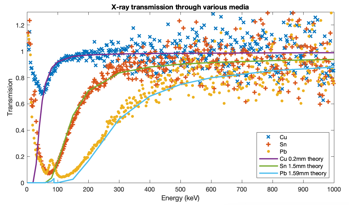
First, to test that the behaviour of each individual metal is understood, a test was run with the instrument shielded by lead, tin (actually pewter) and copper each alone, one at a time. The results shown in Figure 3 closely follow the theoretical preductions based on NIST X-Ray Mass Attenuation Coefficients (DOI 10.18434/T4D01F), Table 3. This shows the result of using each metal alone, rather than assembled into a graded shield.
Finally the three layers were assembled into the full graded shield. Figure 4 shows the observed background through each of lead, tin and copper individually, then lead+tin and ultimately lead+tin+copper. The right panel zooms in to see detail at low energies.
- The lead-only and tin-only curves each peak at their respective X-ray fluorescence lines.
- The lead+tin line lies below lead-only almost everywhere, but pops up above it at the tin X-ray fluorescence peak.
- The lead+tin+copper line lies below lead-only everywhere.
- Above 120keV all the graded shield lines are the same since only the lead is really contributing.
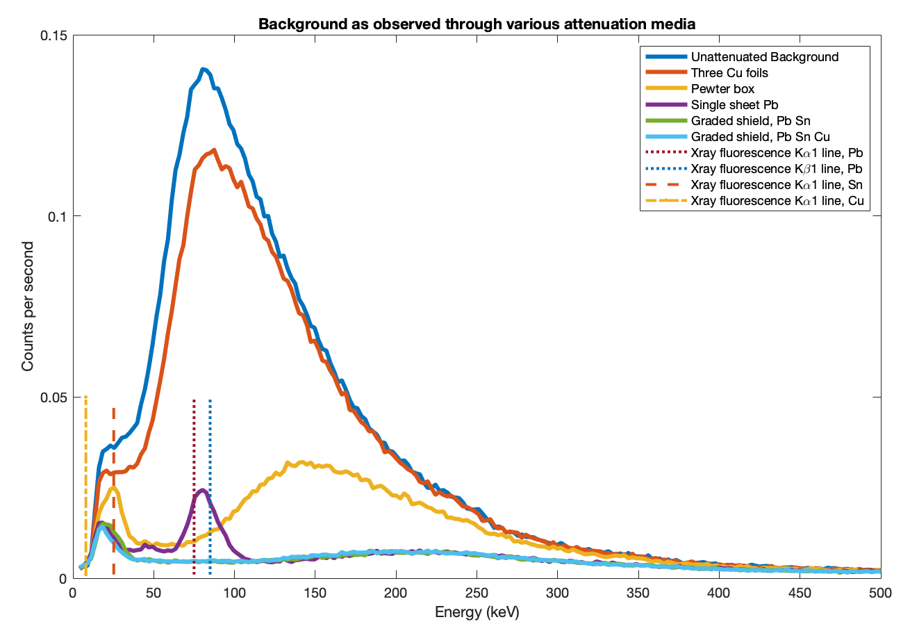
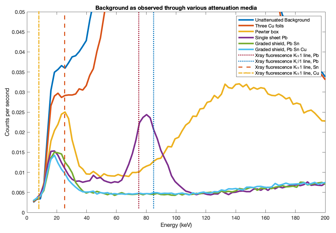
Finally, I address the main apparent failing of the shield. All the data, even the final three layer lead+tin+copper shield, show a low energy peak around 18keV which does not seem to change for any combination of screen materials. At such low energies, 1.6mm of lead should block essentially all photons (actually 99.99999...999% with over one hundred nines). Even the 0.2mm copper foil I am using should block 99.8% of 18keV photons. I believe the final residual signal we see here is the intrinsic background of the instrument itself. I.e., it is not environmental radiation being detected, but the spectrometer itself 'glowing'. No amount or type of external shielding can eliminate this. The one further improvement that could be made is that adding more lead would reduce the low, broad hump in the range 120–400 keV.
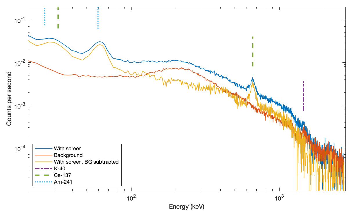
So does it actually work?
The total background over the full spectral range is reduced from 7.65 counts per second (cps) to 1.29 cps, so we still see 16% of original background. Almost all of that is the high energy background, >300keV, where the thin lead is having little effect. More impressively, at 83keV where the background radiation peaks (see Figure 1), the signal is reduced from 0.14 cps to 0.0046 cps, or 3.2%.
The existence of the internal instrumental background suggests that even with the shielding, there is still reason to use background subtraction. If you still need to perform background subtraction analysis with or without the screen then there may be less value in using it. Next I demonstrate real world results for a weak radioactive source, illustrating how much benefit the screen offers. For this test I use a small piece of trinite, integrating signal for one day with and without the screen. The sample shows Cs-137 and Am-241, easily visible with less than an hour of integration. There is K-40, though that could be environmental background from my local geology. Other weak features in the spectrum are difficult to identify and will need substantially longer data collection runs.
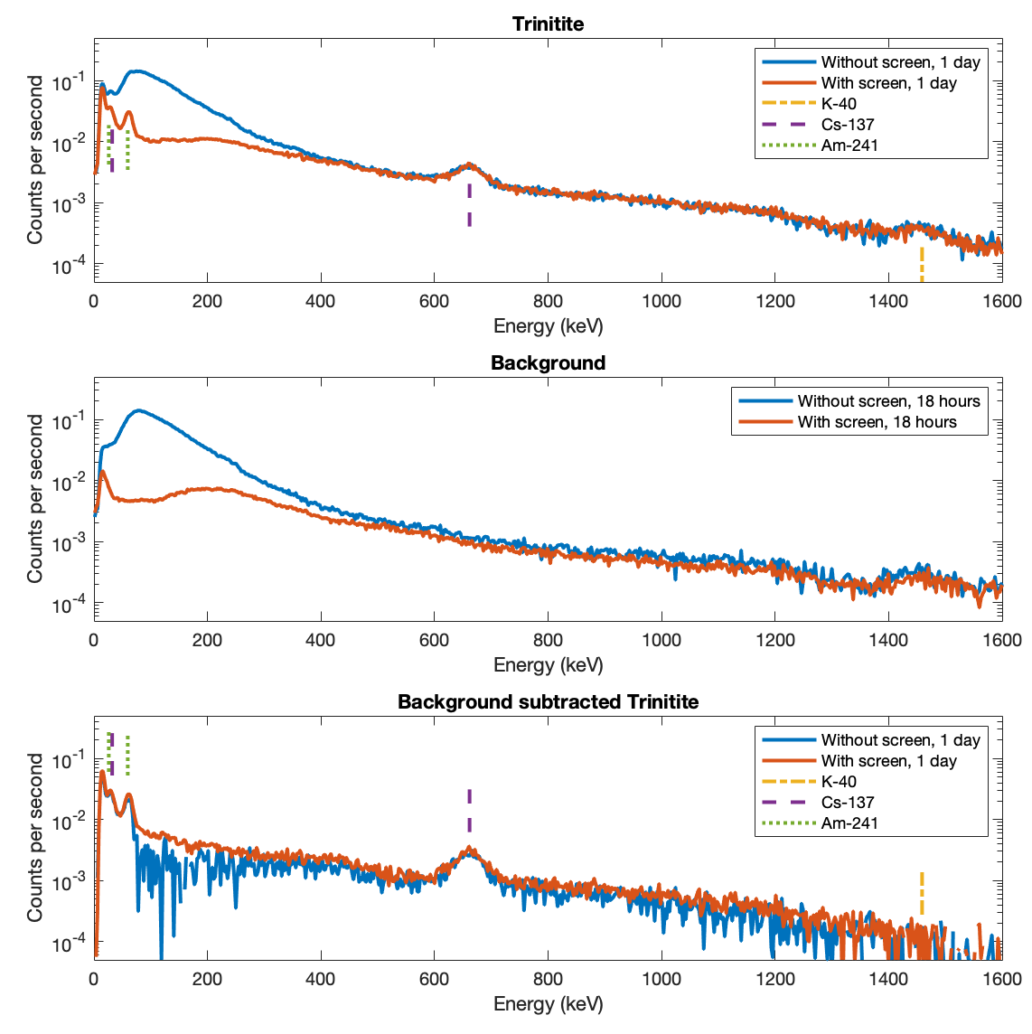
The strong cesium line is easily detected with or without the shield and irrespective of background subtraction. This is because the background is already fairly low at >600 keV. The difference from using the shield is evident at low energies. In the top panel, you cannot see the americium at all without the screen. In the bottom panel, the americium is clear after background subtraction, but the spectrum is very much noisier and less smooth than the screened spectrum. The spectrum obtained inside the graded screened enclosure is undoubtedly superior.
The K-40 line in the raw data is completely subtracted off by the background subtraction, showing that that is in my local ambient background, not in the trinitite sample. This is another illustration that even with the screen you still need to perform background subtraction. The thin lead screen is having little effect above 300 keV.
What it looks like & how much it cost
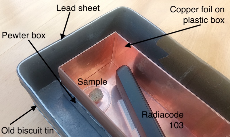
There is nothing clever or special about the design. It really is just a copper box inside and pewter box inside a lead box. The copper box is multiple layers of self-adhesive copper foil on the inside of a 3D printed plastic (PETG) frame, the pewter box is an old jewelry box, and the lead box is lead sheeting stuck to the inside of a biscuit tin. The air gaps between the three effective layers are irrelevent.
Some items I bought new because it was quick and easy. With patience, advance planning and some hunting around you can likely build a similar screen quite a bit more cheaply than I did. My bill of materials was a rather extravagent, just under $100. Prices are US dollars (2023–2024). For comparison the Radiacode spectrometer itself currently (2024) costs €250–300 so at least I can claim to have spent less on the box than the contents!
- Old biscuit tin to use as structural basis of the box, $3 from local charity shop.
- Two square feet of new 1/16" lead sheet, $35. This is where more imagination about finding reclaimed building materials could really reduce the cost.
- Second hand pewter jewelry box, $30.
- 0.2 square meters of self adhesive 0.1mm copper foil, $21. You can definitely buy copper tape cheaper than this, but I selected a retailer that specified the thickness of the copper, the self adhesive glue and the backing paper separately. Many of the cheap foil tapes I found advertised a thickness, but from their weight and the denisty of copper, you can easily calculate the foil could not have been even half the claimed thickness. Many layers of cheap thin foil would work just as well.
- Rather more of my own time than I care to admit
Should I line my house walls with lead?
No.
Lead is highly toxic so this is obviously a bad idea, though other dense metals such as tungsten also make effective radiation shields. In any case there is very little to be gained. All the discussion above is presented in terms of photon counts. Living inside the graded shield would 'protect' me from a large fraction of the gamma ray photons, but it would only be protecting me from the largely harmless low-energy photons. When discussing biological harm, you need to consider the radiation 'dose'. A small number of high energy photons do more harm than a large number of low energy photons. Dose equivalent radiation is measured in Sieverts (Sv). Though you see from the left-hand panel of Figure 4 that the shield is blocking 'nearly all' of the background, the dosage rate only fell from 113 nSv/h (nano-Sieverts per hour) to 81 nSv/h. This makes sense intuitively. We evolved as living creatures in this environment, so it is reasonable that we evolved in a way that the typical ambient conditions were not particularly lethal. Fish typically do not drown and moles are (presumably) not taphophobic.
2024-02-24 4:43 PM
If you have comments or suggestions feel free to contact me: