
The fundamental requirement of a snap-shot HSP system is to take the photograph at the desired stage in the process evolution. The HSP system must therefore be a control system. Suitable control systems range from amazingly simple to extraordinarily complex. The tips on the following sections are designed to help you select the type of control system you wish to build and use. The notes given here are by no means definitive. They merely intend to provide inspiration for your own creativity. Although the fundamental concepts presented here can be applied to any type of HSP control system, there is a bias towards computer controlled systems.
All control systems can be classified into one of two broad types - Open Loop and Closed Loop. The difference between them is the use of feedback via input signal. For the DIY high speed photographer, the difference equates to reliability, expense and simple electronics.
Open loop control systems do not use feedback. This means that the control system assumes the commands it sends have performed their duty precisely. However, this is rarely the case, and open loop control systems tend to be more error prone and less reliable than their closed loop counterparts. The use of open loop control systems for HSP is not recommended, though it does provide the least expensive approach. To illustrate the open loop concept, lets revisit the example of the splash produced by a water drop. Our control system will provide commands to release a drop of water and fire the flash gun some specified time later. Although this might seem adequate for the job, the results are likely to be inconsistent. The problem arises with the release of a drop, since every drop is likely to begin free-fall at a slightly different time after the command was given to release the drop. Since the control system is oblivious to this effect, and fires the flash gun at the time the drop was expected to reach the surface below, there will be a timing error, producing inconsistent results. It is not fair to say that open loop controls for HSP will not work, just that they will be far less reliable than the corresponding closed loop control system.
The simplest of simple open loop HSP systems is the human. You can attempt to initial the processes by hand (ie. squeeze an eye-dropper) and press the manual fire button on the flash gun at the moment you expect the process to be evolving (ie. drop splashing on the surface below). What makes this job difficult for the human control system is that it must be done in absolute darkness (NB - with lights on, your eyes can watch the process evolving, providing the feedback required to make the human a closed loop control system).
The role of feedback in a control system is simply to provide additional information that can be used to attempt to reduce errors. For example, a robotic arm might use encoders to measure the position of the joints in the arm. The measured positions can be compared to the position the control system instructed them to move, and addition control instructions sent to move the joins to reduce the position errors. The important elements in the closed loop system are the sensors that provide information about the environment (ie. is the drop in free-fall; was there a noise produced; have two objects collided etc.), and the processor that decides what to do with the information received from the sensors. Designing and constructing control systems of this type require a little more thought, but the rewards are considerable.
We again return to the water drop example. A closed loop control system could be created by adding an infrared beam switch to the electronic open loop version. However, instead of beginning the time delay when the command is given to release a drop, we wait for the drop to trigger the infrared switch as it passes through the beam in free-fall. Once the signal from the IR-switch is received, the time delay begins. This reduces the timing error considerably and results in a reliable, repeatable experiment.
Simple electronics provides the foundation for many closed loop control systems. Since the principle components that we would wish to control for HSP are electronic in nature, an electronic control system is the natural choice. As this document is not designed to be a course in electronics, only general concepts shall be presented, and our system as an example. The choice of available power supply should be considered before designing circuits. Old personal computers are a great source of cheap yet versatile power supply units. These will usually provide terminal voltages at -12V, 0V (GND), +5V and +12V. This will allow the use of dual rail operational amplifiers, digital logic devices (TTL and CMOS) along with the traditional single component devices (transistors, relays, SCRs etc.). Less versatile alternatives are batteries and +12V transformers. Once a power supply has been selected, your attention can turn to the functions you want your control system to exhibit.
The basic requirement of any HSP control system is the ability to fire the flash gun. The electronics required to do this may depend on the particular flash gun you have, so some experimentation may be required. For all flash guns, the flash is fired by closing a switch. Although this seems very straight forward, we need this switch to close when given an electrical signal. There are (at least) three devices that can operate a "switch" is response to another electrical signal. We consider each in turn.
A relay is an electromagnetic device. It used a small electromagnet to mechanically close a pair of switch contacts. They have the advantage that the circuit that controls the electromagnet and the circuit involving the switch are electrically separate. Relays are commonly used in automotive applications to switch on a large current with a much smaller current in the electromagnet. Their primary disadvantage is that they respond very slowly, and therefore they are not ideally suited to the task of firing the flash for HSP. However, they are very useful for other applications in more complex HSP control systems. Relays are also relatively expensive ( as far as electronics goes ).
A much faster switch can be created from a bipolar transistor. These three terminal (leg) devices allow current to flow between two of the terminals (collector and emitter) when a much smaller current is flowing from the third terminal (base) to the emitter. Effectively, a signal sent to the base of an NPN transistor can create a closed switch between the emitter and collector. The correct choice of transistor depends on the voltages that will be placed across the terminals, and the current that is to flow through the circuit. This is a rather narrow and oversimplified view of the transistor. For the inexperienced that wish to depart from the examples circuits here, or in the links, consult a suitable electronics reference (The Art of Electronics, by Horowitz and Hill would be a good choice). The greatly reduced response time of the transistor comes at the expense of polarity and coupled circuits. This means the direction that current is to flow through the device is important, and that the electronics on the switch side and control side of the transistor are connected together.
For many flash guns (our primary concern here), the voltage across the terminals that must be closed to fire the flash is quite high (typically 300V). Unfortunately, transistors are not normally suitable for such high voltages. We therefore recommend that a transistor is not used to operate the flash unless you are certain that the transistor specifications are appropriate for the flash terminal voltage. In general, transistors will be an essential element in other HSP control system applications.
An SCR is an extension of the bipolar transistor, with a few peculiar properties. Firstly, it capable of switching high voltages (400V SCRs are sufficient for commercial flash guns). Secondly, once an SCR has been switched on by the control signal, it does not switch off again until the supply voltage (being switched) drops to almost zero. For a flash, this means the switch stay on until the flash has fully discharged. Like the bipolar transistor, the SCR is a three terminal device and it is polarised. The terminals are called the source, drain and the gate. Current will flow from the source to the drain when the gate voltage is raised about 1V above the drain. An SCR would typically be used for the flash gun only.
The previous section was concerned with switching on the flash gun in response to a control signal. However, the devices described can be applied to control a variety of other components. For example, we may also want the control system to open the camera shutter and turn on and off a motor or electromagnet. The choice of control device should take into consideration the require timing precision as well as the current and voltage specifications of the device.
In order to construct a closed loop control system, we must have some form of input device to provide feedback. In precise positioning control systems, a wide range of values can be measured and used as feedback. In simple HSP systems, our input signals are normally used as a trigger for a binary control system. (ie, the flash gun control signal is turned on when a noise is detected or an IR beam is broken). This can often be broken down into three separate pieces. The first is the transducer, which provides an electrical signal in response to its environment. The second stage is amplification which boosts the, usually feeble, signal from the transducer. The third stage is comparison, which produces the control signal if the amplified input signal is above (or below) a preset threshold.
It is rare that the you will want to fire the flash gun at the instant the input device produces the triggering signal. Therefore, a short and precise time delay is required. A simple electronic time delay unit should have an input, an output and a means for presetting the delay time. When the input signal changes, the output signal will change to match the input signal after the time delay. This kind of device could be constructed using either digital or analogue electronics techniques. The commercially available 555 timer chip is probably the simplest method for stand-alone HSP systems. Since the 555 chip has digital inputs and outputs, the control signal issued by the input electronics should be 0V for the off state and +5V for the on state. Similarly, the flash should fire when the control signal goes from 0V to +5V.
In it's simplest form, the HSP control system can be thought of as the three separate modules described in the electronics section (Input,Time delay and Control). The "stand alone" electronics approach sees these modules constructed in electronics hardware. A personal computer provides a software alternative for the time delay module, and a flexible platform for binding together many other modules. This still requires the construction of electronics hardware for input signals and control signals, though the modules can be made simpler than their "stand alone" counterparts. However, the gains made by simplifying the electronics are offset by the requirement that software must be written to implement the core of the HSP control system. The advantage of software implementation is the ease with which changes can be made to improve the system, and correct mistakes. It also provides a platform for developement.
Since the input and control signal modules must still be constructed from electronic circuit, we need a method for coupling these components to the electronic circuitry of the PC. There are a variety of methods available, though the parallel port is arguably the simplest and most effective interface.
The parallel port provides a simple, yet versatile means of interfacing small electronic devices with a PC. Although use of this port has long been the domain of the printer, it can accommodate a wide variety of other devices, including a HSP I/O device.
Although different implementations of the parallel port provide slightly different functionality, we shall take the "common to all" approach to the parallel port. For a detailed discussion of the parallel port, consult one of the references in the links page.
The parallel port is in fact composed of three ports - DATA, STATUS and CONTROL. The byte written to or read from these ports sets or observes the digital state of the signal lines with which they are associated. The DATA port is an output port with 8 signal lines, and the address of the port is the base address of the parallel port. The CONTROL port is also an output port, though there are only 4 external signal lines. The base address of the CONTROL port is the the base address + 1. The STATUS port is an input port with 5 external lines, and one of these has a dual function. The address is the base address + 2. All of the external signal lines are accessed via a D25 pin plug. Signal ground lines are also accessible via the D25 plug. The digital state of each output control line is determined by the state of 1 bit in the corresponding port. For example, pin 4 on the D25 plug corresponds to bit 2 of the DATA port. If the byte written to the base address of the parallel port has bit 2 set to 1, then the output state of line 4 is high, or approximately +5V. Alternatively, if the bit was set to 0, the line output state would be low, or approximately 0V. Some of the signal lines in the CONTROL port are inverted. This means if the corresponding bit is 1, the output state is low, and if the bit were 0, the output state would be high. Inverted or not, the output lines of the DATA and CONTROL ports provide 12 digital signal lines, the states of which can be controlled separately by software. The details of electrical connection to these line will be treated in a later section.
The STATUS port provides 5 lines onto the I/O bus of the PC. The software approach to the input signal lines is simply to read the byte in the port. Each bit in the byte held in the STATUS port, corresponding to an input line, is dependent on the digital state of the input line. Again, some of the input lines are inverted, so that the relation between electrical state, and the corresponding bit depends on the particular line. Either way, we can determine the state of 5 independent input signals with software. Again, electrical connection to the input lines of the STATUS port shall be treated in a later section.
The DATA and CONTROL ports are both latched. This means the output signals are set when a software operation writes a byte to the port, and the output remains unchanged while other software operations are performed.
Electrical connection to the parallel port is relatively straight forward for both input and output lines, though a few simple rules must be exercised. The output lines on a parallel port (DATA and CONTROL) are TTL (transistor- transistor logic) and are capable of sourcing about 2.5mA or sinking about 20mA. The choice between sourcing or sinking current to drive a load is dependent on the load, though sinking current is the favoured method. The primary difference is the requirement for an external power supply, though one is usually required anyway. When sourcing current from the TTL output lines, power to drive the load is supplied from the port when the line is in the HIGH state. When sinking current, power to drive the load is provided by an external +5V supply, and current flows through the load when the output line is in the LOW state. Electrical connection to input lines is a little more tricky. The parallel port is connected to the I/O bus, which means that many devices have a common link to the CPU. To ensure that input from different devices do not interfere and overload the bus, each device must be able to decouple its signals from the bus. For input lines, this can be done in one of two ways - tri-state drivers or open collector transistors. Tri-state drivers are commonly used in commercial devices, but open collector transistors are a simpler alternative. The collector of an NPN transistor is connected to the input line, the emitter is connected to ground, and the input signal drives the base (through an appropriate resistive load). When the input signal to the base is low, the transistor will not conduct between the collector and emitter, and the transistor is said to be in an open state. The signal on the bus can change due to another device, unaffected by the transistor. When the input signal goes high, the transistor will conduct between the collector and emitter, and the bus signal will be pulled into the LOW state. Each bus line is connected to +5V through a resistive load. If all devices are in the open state (signal low, or decoupled) then the bus is held at +5V, and hence is HIGH. However, if any of the devices connect the bus to ground by transistor conduction, the bus signal will go LOW. Due to the interconnection of devices on a bus, it is imperative that bus lines are never driven by totem pole devices (ie, logic gates - they are either high or low, never open ).
| PIN | Name | Port | bit | Logic |
|---|---|---|---|---|
| 1 | Strobe | Control | 0 | Inverted |
| 2 | data0 | Data | 0 | Normal |
| 3 | data1 | Data | 1 | Normal |
| 4 | data2 | Data | 2 | Normal |
| 5 | data3 | Data | 3 | Normal |
| 6 | data4 | Data | 4 | Normal |
| 7 | data5 | Data | 5 | Normal |
| 8 | data6 | Data | 6 | Normal |
| 9 | data7 | Data | 7 | Normal |
| 10 | ACK | Status | 6 | Normal |
| 11 | BUSY | Status | 7 | Inverted |
| 12 | Paper Out | Status | 5 | Inverted |
| 13 | Select In | Status | 4 | Inverted |
| 14 | Auto Line-feed | Control | 1 | Inverted |
| 15 | Error | Status | 3 | Inverted |
| 16 | Init | Control | 2 | Normal |
| 17 | Select | Control | 3 | Inverted |
| 18 | Ground | Ground | - | --- |
The core of a PC HSP control system is the software. It is at this level you can implement time delays and provide flexibility. It is also true that a considerable programming effort will be required to achieve this. However, simple software is the best starting approach. The basics are shown here as code fragments for the Borland C/C++ and Pascal programming languages. For C/C++, the dos library function will b=need to be included using # include <dos.h>. The corresponding code in Pascal is uses dos.
Controlling your HSP peripheral is simply a matter of writing bytes to
the DATA and CONTROL ports to set the output lines high or low, as required.
In the following example, we'll assume that the base address of the parallel
port is hexadecimal 378, and the flash is connected to pin 6 on the D25 plug,
which is bit 4 on the DATA port. The instructions to turn on the flash, is
then:
C/C++
         outportb(0x378,16);

Pascal
         port[$378] := 16;
Both of these instructions are simply writing the bits 0001000 to the DATA
port. (Note decimal 16 = binary 0001000). To turn the flash off and allow it
to recharge, the byte 0 would be written to the port.
Reading an input signal from the port is just as easy. For example, lets
assume that the output from the sound trigger is connected as an input to bit
5 of the status port. Now, since we use an open collector transistor to connect
the input signal to the port, a sound will set the bus signal to LOW. However,
bit 5 of the status port is inverted, so that bit 5 will be 1 when the
sound trigger produces a signal. Now, since we would usually wait for a signal
before starting some other action, our code will poll the port until a sound
is recorded by the sound sensor.
C/C++
         while (inportb(0x379)!=32);

Pascal
         repeat i := port[$379] until i==32;
With these instructions, the STATUS port is read continuously, until the
value of the bits at the port is 00100000. Note, that if another input device
on the HSP peripheral was producing a signal, the boolean condition would
never be true. A better method would be to perform the bitwise AND operation
so that only the value of bit 5 was relevant.
A time delay is easily obtained by waiting a certain number of CPU clock
cycles, as shown in the examples
C/C++
         counter = 10000;
	 while (--counter);

Pascal
         counter := 10000;
	 repeat counter := counter - 1 until (counter = 0);
In both cases, the counter variable is repeated decremented until its value
is zero.
These three examples can now be collated into a very simple program that
asks the user for a time delay, waits for the signal from the sound trigger,
waits the specified time, fires the flash and then turns off all output
signals.
C/C++
         # include <stdio.h>
         # include <dos.h>

	 void main(void) {

	   long counter;

	   /* initialise */

	   outportb(0x378,0); /* DATA */
	   outportb(0x37A,0); /* CONTROL - unused */
	   /* ask the user for a positive time delay value */

	   counter = -1;
	   while (counter<0) {
	     printf("Enter a time delay :-\n");
	     scanf("%ld",&counter);
           }

	   /* wait for signal */

	   while ((inportb(0x379) & 32) != 32);

	   /* time delay */

	   while (--counter);

	   /* fire flash */

	   outportb(0x378,16);

	   /* turn off all output signals */

	   outportb(0x378,0);
	   outportb(0x37A,0);
         }


Pascal

         program hsp;

	 uses dos;

	 var
	   counter:longint;
	   i:integer;

	 begin

	   port[$378] := 0;
	   port[$37A] := 0;

	   counter := -1;
	   repeat begin
	     writeln(' Enter time delay :');
	     readln(counter);
	     end;
	   until (counter >= 0);

	   repeat i := port[$379] until (i==32);

	   repeat counter := counter - 1 until (counter = 0);

	   port[$378] := 16;

	   port[$378] := 0;
	   port[$37A] := 0;

         end.
The following is a brief description of the HSP system designed and built by the authors.
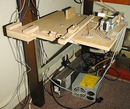
The completed circuit board, mounted on craftwood, is shown below.
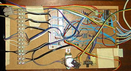 The HSP system we constructed was designed to be versatile and extensible.
Three types on input signal were incorporated; Sound, IR Gate and push-button
contact. Devices for control include an SCR for the flash, Darlington
transistors for motors and Relays for electromagnets and direct contact
switches. Time delays are implemented in software. All controllable devices
are connected to the board via terminal blocks to aid transportation and
make for easy hardware changes. Input devices are directly connected ( though
I wish they were not - plugs and sockets would have been better ). Connection
to the parallel port is via a D25 plug, and is normally connected though an
extension cable. The interface board was made using a prototype PCB. Power
for the board is derived from an old PC power supply unit (PSU).
The HSP system we constructed was designed to be versatile and extensible.
Three types on input signal were incorporated; Sound, IR Gate and push-button
contact. Devices for control include an SCR for the flash, Darlington
transistors for motors and Relays for electromagnets and direct contact
switches. Time delays are implemented in software. All controllable devices
are connected to the board via terminal blocks to aid transportation and
make for easy hardware changes. Input devices are directly connected ( though
I wish they were not - plugs and sockets would have been better ). Connection
to the parallel port is via a D25 plug, and is normally connected though an
extension cable. The interface board was made using a prototype PCB. Power
for the board is derived from an old PC power supply unit (PSU).
Circuit diagrams for each module are shown below.
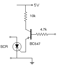 |
The charged flash gun will fire when the control signal goes from TTL low to TTL high. This sends the BC547 transistor into conduction and raises the SCR gate voltage above the drain. The SCR then goes into conduction and the flash discharges. |
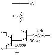 |
This circuit is simply designed to drive larger current loads than a single transistor controlled by the parallel port can achieve. Here, the signal to the base of the BC547 transistor is amplified to provide a signal large enough to drive the base of the BC639 transistor, which has a higher current rating. Alternatively, a darlington transistor package could be used ( I simply didn't have one when it was needed. ) |
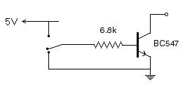 |
When the switch connects the common pole to GND, the base of the BC547 transistor is held at GND, the transistor does not conduct, and the input signal is open. Toggling the switch to connect the base to +5V sends the transistor into conduction and the collector is pulled to GND, providing the active input signal for the STATUS port. |
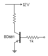 |
The BD681 transistor is a darlington package. The TTL signal from the CONTROL port drives the base of the transistor, energising the winding (unlabeled resistor) of the stepper motor phase. Four of these modules are required for a bipolar stepper motor, one for each phase. Energising a motor phase causes the rotor to move a finite amount ( a step). The motor can be made to spin continuously by repeating the cycle of energising all four phases in turn. ( The phase sequence must be correct for this to occur. ) |
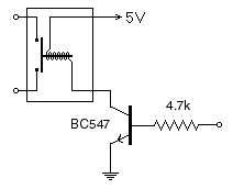 |
The base of the BC547 transistor is driven by the DATA port, amplifying the signal, which energises the winding of the electromagnet in the relay. This closes the switch contacts. |
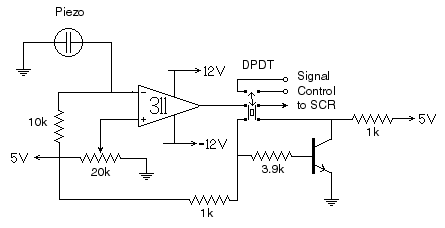 |
A sharp sound causes the collector voltage (output) on the LM311 comparator to go from open to GND. The sound level that causes this can be adjusted by setting caparison voltage with the 20k potentiometer. The DPDT switch allows the signal to be sent to the STATUS port, or connected as a direct trigger to the SCR. In the case of the former, the control signal for the SCR is connected to the DATA port. In the later case, the signal is invered by the BC547 transistor and sent to the SCR. |
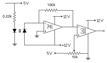 |
IR radiation from the IR led enters the IR photodiode, producing a small voltage, whi is then amplified by the LM741 operational amplifier. The amplified voltage is comared to a reference voltage using an LM311 comparator. The collector of the comparator is connected to the STATUS port, and the signal toggles between GND and open when the IR beam is blocked. The refernce voltage for the comarator is set with the 10k potentiometer. |
 One of the objectives of our system was control for initiating action. This
is why there are more control devices than simply an SCR for the flash. We
found it desirable to control the camera shutter with our system, rather than
by hand. We also constructed a clamp with an electronically controllable
release mechanism. This is very useful for dropping objects so that the place
they hit the ground is consistent (it is very hard to do this by hand in the
dark). A stepper motor and electromagnet are used to load and release the
clamp respectively.
One of the objectives of our system was control for initiating action. This
is why there are more control devices than simply an SCR for the flash. We
found it desirable to control the camera shutter with our system, rather than
by hand. We also constructed a clamp with an electronically controllable
release mechanism. This is very useful for dropping objects so that the place
they hit the ground is consistent (it is very hard to do this by hand in the
dark). A stepper motor and electromagnet are used to load and release the
clamp respectively.
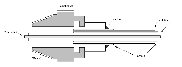
Controlling the camera shutter with the HSP system is electronically
trivial, but rather delicate. The cable release on my camera (Minolta X-1)
pushes on the leaf of a switch, closing the contacts and creating the circuit.
However, the circuit can also be formed by electrical contact between the
leaf of the switch, and the camera body. To make use of this feature, I
used the treaded tip of an old cable release, and fitted it over a shielded
cable. The insulation on the inner conductor was removed at the tip, which
protruded out the end of the threaded connector. The braided shield was folded
back over the outer insulation and made electrical contact with the threaded
connector by soldering them together. The length of the inner conductor was
adjusted so that it just made contact with the leaf of the switch when the
connect was fully threaded into the cable release socket. Now, the inner
and outer conductors of the shielded cable can be connected together to open
the shutter. These were connected to the switch poles of a relay to allow
the camera shutter to be controlled in software. A schematic of the modified
connector is shown below.
An alternative method could use the contact on the base of the camera body
designed for automatic winders ( Many cameras only have the contact for the
camera to signal to the winder. The automatic winder for your camera would
need to have its own shutter button for this to be an option.) For either
method, considerable experimentation with your camera will be required.
Yet another alternative is to connect an electromagnet to a cable release and
mechanically push the contact. This method is effective, though somewhat
cumbersome. (I've found that the cable release needs to be kept quite straight
for this method to work with cheap electromangets. )
The software we use to control the HSP board has had several iterations. The current model is a completely configurable version, with a layered menu interface. It was far more an exercise in C++ than in HSP control. However, there are some important concepts that should be incorporated into the control system. Firstly, it is imperative for consistent timing that interrupts from other devices do not stop the HSP program during the action sequence. The most likely offender is the DOS clock interrupt, which occurs at a frequency of 18.2 Hz. To prevent this interrupt, the interrupt mask must be changed at the beginning of the program, and changed back again at the end. To prevent the interrupt, the byte at port Hex21 should be changed to the logical value of itself AND HexFE. The original value should be saved to reset port Hex21 before the program exits. ( See the links for a thurough discussion of this topic. ) The other key concept is modularity. Write procedures or member functions to keep the operation of the system consistent for all types of control sequences. Procedures used for measuring a time delay ( while experimenting on the setup ) should return a number that is useful when it comes time to do the experiment for real.
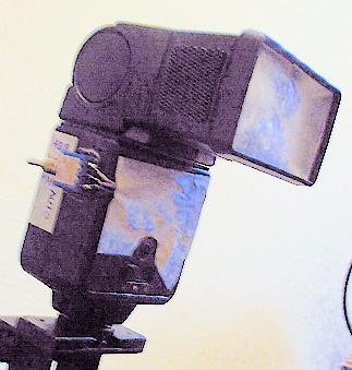
After several roles of film it became apparent that the flash pulse was not
as repeatable as we would have liked. The length of the flash pulse was rather
dependent on the subject, and the exposure on the film was quite variable.
This is largely due to the nature of the automatic flash gun. It can achieve
very short flash pulses, but the primary function of the flash is to provide
the right amount of light for the correct exposure. The ideal scenario is
a short flash pulse that is independent of the photographic subject. In an
attempt to achieve this, some minor modifications to the flash gun were made.
The crucial element in the automatic flash is the thyristor, which measures
the light reflected from the subject and cuts off the flash pulse to produce
the correct exposure. We simply replaced the thyristor with a resistor,
allowing the flash pulse to be cut off, making the pulse short and consistent.
Some experimentation was required to choose the resistance that produced the
right compromise of pulse length and total light. So that the flash was not
rendered useless for other photographic applications, the resistor was placed
in parallel with the thyrisitor, and a toggle switch used to select the use of
thryistor or resistor. The modified and taped-up flash gun is shown in the
following image.
 The next task was to determine the guide number of the flash when using the
resistor. This is required to determine the lens aperture that will produce
the correct film exposure. Formally, the guide number is the distance of the
subject ( measured in meters ) multiplied by the aperture of the lens that
produces the correct exposure. The guide number of the modifies flash should
be relatively small ( about 3 or 4 meters ). In controlled lighting
conditions, take a photo of a contrasty subject, about 50cm from the camera
and flash, using the camera light meter as a guide for the exposure. Then,
take photos of the same subject with the flash as the only light source.
Repeat this for a wide variety of apertures. It is a good idea to include in
the photo a note with the camera-subject distance, and the f-number. If you
are also experimenting with different resistances, include the resistance on
the note. Once the film has been developed, inspect the negatives to see
which aperture produced a photo with the same exposure as the camera light
meter. Calculate the guide number by multiply the camera-subject distance and
the f-number for the correct exposure. For all subsequence photographs with
the flash in resistor mode, determine the required f-number for the
camera-subject distance from the guide number. ( Note that the camera and flash
are assumed to be at the same place for all of these calculations, as it is
for a flash in automatic mode. Also, it was assumed that the same ASA rating
was used in the guide number determination as will be used for HSP
experiments.)
The next task was to determine the guide number of the flash when using the
resistor. This is required to determine the lens aperture that will produce
the correct film exposure. Formally, the guide number is the distance of the
subject ( measured in meters ) multiplied by the aperture of the lens that
produces the correct exposure. The guide number of the modifies flash should
be relatively small ( about 3 or 4 meters ). In controlled lighting
conditions, take a photo of a contrasty subject, about 50cm from the camera
and flash, using the camera light meter as a guide for the exposure. Then,
take photos of the same subject with the flash as the only light source.
Repeat this for a wide variety of apertures. It is a good idea to include in
the photo a note with the camera-subject distance, and the f-number. If you
are also experimenting with different resistances, include the resistance on
the note. Once the film has been developed, inspect the negatives to see
which aperture produced a photo with the same exposure as the camera light
meter. Calculate the guide number by multiply the camera-subject distance and
the f-number for the correct exposure. For all subsequence photographs with
the flash in resistor mode, determine the required f-number for the
camera-subject distance from the guide number. ( Note that the camera and flash
are assumed to be at the same place for all of these calculations, as it is
for a flash in automatic mode. Also, it was assumed that the same ASA rating
was used in the guide number determination as will be used for HSP
experiments.)
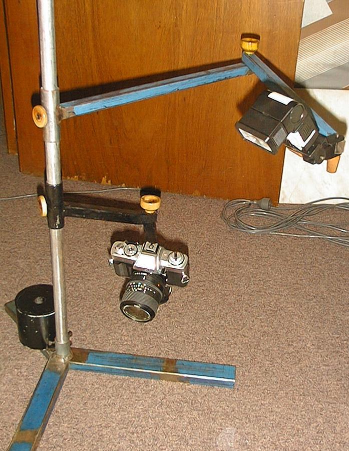 In confined spaces, it can be difficult to setup more than one tripod. Also,
most inexpensive tripods cannot support the camera close o the ground. For both
of these reasons, I built a stand that supports that flash and camera
independently. This is largely a welded steel construction, but a similar
stand could be made from wood. The camera is attached to the stand with a
tripod head. The flash fits into a hot-shoe, that was part of the construction
( though I'd recommend buying, rather than building one of these ).
If you decide to build one of these things, remember that it is going to
support your camera and flash, so make it strong and sturdy.
In confined spaces, it can be difficult to setup more than one tripod. Also,
most inexpensive tripods cannot support the camera close o the ground. For both
of these reasons, I built a stand that supports that flash and camera
independently. This is largely a welded steel construction, but a similar
stand could be made from wood. The camera is attached to the stand with a
tripod head. The flash fits into a hot-shoe, that was part of the construction
( though I'd recommend buying, rather than building one of these ).
If you decide to build one of these things, remember that it is going to
support your camera and flash, so make it strong and sturdy.